In the previous article we have seen about “How to Design Test Cases Using Cause and Effect Graph Testing Technique” Similar way in today’s article we are learning one more interesting test technique used in the software testing called “State transition testing technique”.
State transition testing is a form of Dynamic Testing Technique that comes in use when the system explained as a finite number of states and the evolutions between the states is ruled by the rules of the system. Another use of this technique when features of a system are characterized as states that converts to other state, this transition is explained by the method of the software
The diagrammatic explanation is shown below,
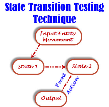
So, the diagram shows that, the input condition has came the reason of an entity transitions from State 1 to State 2 that guides to an event and results to an action and finally gives the output.
Four major parts of state transition model:
- States that the software might get (open/closed or sufficient/insufficient funds)
- The transition from one state to another (with single transitions)
- The events that origin a transition (closing a file or withdrawing money)
- Actions that result from a transition (an error message or being given the cash)
For any given state, one event origins only one action, but that the same event from a different state might origin a different action and a different end state.
An example to explain State transition testing technique:
Go to ATM machine to withdraw $1000, requires to the ATM machine and get cash. Later on, go to the ATM and give the same request at same amount but this time ATM refuses the amount because of insufficient balance amount.
This refusal happened just because of bank account has been changed from one state (sufficient funds) to another state (insufficient funds). The transaction that caused the account to change its state was maybe the earlier withdrawal.
Below diagram shows that how ATM get process using Personal Identity Number (PIN).
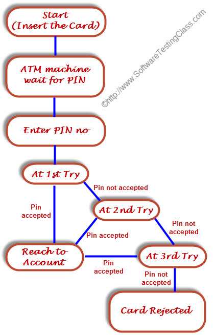
The above state diagram shows several states and four events: Insert Card, Enter PIN, PIN accepted and PIN not accepted). There would also be a transition from the “Card Rejected” state back to the start state.
There should be a ‘cancel’ option at the time of ‘wait for PIN’ process and at the time of three tries that should also go back to the start state and eject the card.
Even think, still this state diagram is incomplete; it also gives us some more information that should be helpful in designing the test cases and explaining the state transition technique.
Let’s take some scenario to develop test cases,
- The first test case should be very much sensible to enter the correct PIN at the first time
- The second test should be to enter an incorrect PIN each time, so that the system rejects the card
- To test all transition, firstly do the testing where the PIN was incorrect the first time but OK the second time and another test where the PIN was correct on the third try
- But, these tests are basically less important than the first two tests
The major advantages of the state transition technique is that the model can be as detailed or as abstract as you need it to be. Where a part of the system is more significant a larger depth of detail can be modelled. Where the system is less important, the model can use a single state to indicate what would otherwise be a series of different states.
The Coverage of single transition is also called as 0-switch coverage, the coverage of pair’s transition is 1-switch coverage, coverage of triples transition is 2-switch coverage, etc.
Explaining test cases from the state transition model is a black-box approach. Determining how much test has been completed is a white-box perspective. However, state transition testing is regarded as a black-box technique. Determining tests simply from a state graph (also known as a state chart) is wonderful for looking the valid transitions, but we may not simply look the negative tests, where we try to make invalid transitions. In order to see the total number of mixtures of states and transitions, both valid and invalid, a state table is useful.
Table below shows the state table lists all the states down at one side of the table and all the events that origin transitions along the top (or vice versa). Every cell then symbolizes a state-event pair.
The information of each cell shows which state the system will shift to, when the resultant event arises while in the associated state. This will contain possible erroneous events – events that are not accepted to happen in certain states. These are negative test conditions.
| Insert Card | Valid PIN | InValid PIN | |
| Start State | S2 | – | – |
| Wait for PIN | – | S6 | S3 |
| 1st try invalid | – | S6 | S4 |
| 2nd try invalid | – | S6 | S5 |
| 3rd try invalid | – | – | S7 |
| Access Account | – | ? | ? |
| Card not excepted | S1 (for new card) | – | – |
This Table shows different states in the first column and the respective inputs across the top row. For Example:
- Suppose the system is in state 1, after inserting the card it will go to state 2.
- If system is in state 2, after entering a valid PIN, it goes to State 6 to access the account. In State 2 if we enter an invalid PIN it goes to State 3.
In the table, a dash (-) sign represents invalid transitions of that state. A question mark in two cells – either a valid or invalid PIN, when we are using the account. Possibly the system will catch our PIN number as the amount of cash to withdraw? Other invalid cells would be actually not possible in this example. Invalid (negative) tests will try to make invalid transitions, transitions that shouldn’t be possible.
If you enjoy reading this article please make sure to share it with your friends. Please leave your questions/tips/suggestions in the comment section below and I’ll try to answer as many as I can.
Don’t Miss Another Article
Join over 10,000 people who get FREE and fresh content from this Blog.
We Respect Privacy, You’re Safe! No Spam!

3 thoughts on “How to Design Test Cases Using State Transition Testing Technique?”
Good example. I am looking for the exploratory testing article, can you share me?
Varsh: You can check exploratory testing article on https://www.softwaretestingclass.com/what-is-exploratory-testing/
Hi,
I’m preparing to ISTQB exam and I’ve got a big problem to understand how 0-switch and 1-switch works correctly. How test cases should be designed?
It’s really important I don’t know if I understand well this concept (these questions often appear an exam)
Can you explain me this problem for above example?
I think about one example for 0-switch and 1-switch I can’t find good example anywhere!
Many thanks for your help
Regards
Lukas